To accurately simulate a structure’s behaviour using the Finite Element Analysis (FEA) method, it’s crucial to incorporate an elastic-plastic strain analysis. However, in many cases, only an elastic analysis is conducted to circumvent the time and expense associated with elastic-plastic analyses. Due to the intricate geometries of most structures, such as discontinuities and stress concentration regions, areas with stresses surpassing the yield point are often observed when analysed elastically. These high-stress zones, if not attributed to singularities or modelling issues, indicate potential local material yielding. Acceptance of such plastic zones hinges on ensuring that the total strain remains below a reasonable threshold, allowing localised plastic deformation without overall fracture or failure.
Glinka’s strain energy method is commonly utilised to estimate the combined elastic and plastic strain from linear analysis results. This method shares close ties with Neuber’s approach, which enables the conversion of fictitious, entirely elastic stress values obtained from FEA into realistic elastic-plastic values. This conversion is fundamental for any computation involving local elastic-plastic strain analysis, except for cases involving transient analysis.
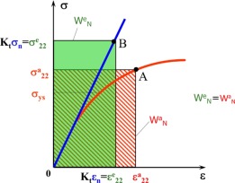
The following diagram illustrates the application of Neuber’s rule. The stress σe represents the maximum stress obtained from an elastic Finite Element Analysis (FEA), whereas εp denotes the actual total strain in an elastic-plastic material model. The figure incorporates a Ramberg-Osgood line, which is a non-linear stress-strain model commonly used for ferrous materials.
The Ramberg-Osgood model is a mathematical representation used to describe the nonlinear stress-strain behaviour of materials, particularly metals like steel. It provides a way to characterise the material’s response to stress beyond the linear elastic range, where the relationship between stress and strain becomes nonlinear.
Reference: https://www.sciencedirect.com/science/article/pii/B978012819293100019X
In this model, the stress-strain curve is typically represented by a mathematical equation, which takes into account both elastic and plastic deformation. The equation is often expressed as:

Where:
σ is the stress,
ε is the strain,
n is a material constant related to the material’s strain hardening behaviour,
σy is the yield stress.
The Ramberg-Osgood model allows for a more accurate representation of the material’s behaviour under various loading conditions, including cyclic loading and large deformations. It is commonly used in finite element analysis (FEA) and other numerical simulations to predict the mechanical response of structures and components made from metallic materials.
Eurocode 3 permits a maximum total strain of 5% (0.05) under ultimate loads. To define a criterion for accepting peak FEA stresses, this value is reduced by the capacity reduction factor of φ=0.9 (AS 4100), resulting in a 4.5% maximum limit state strain. The corresponding limit state stress is calculated using the Ramberg-Osgood equation.